Shapes
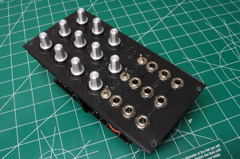
A triple VCO. Two that are switchable between square with PWM and sawtooth. One switchable between sawtooth and triangle. This is based on Moritz Klein's DIY VCO series on Youtube. It was my first foray into the world of modular synthesizers and his videos are incredibly in depth and a great way to start your learning experience. Go check out his videos!
Explanation of the Circuit
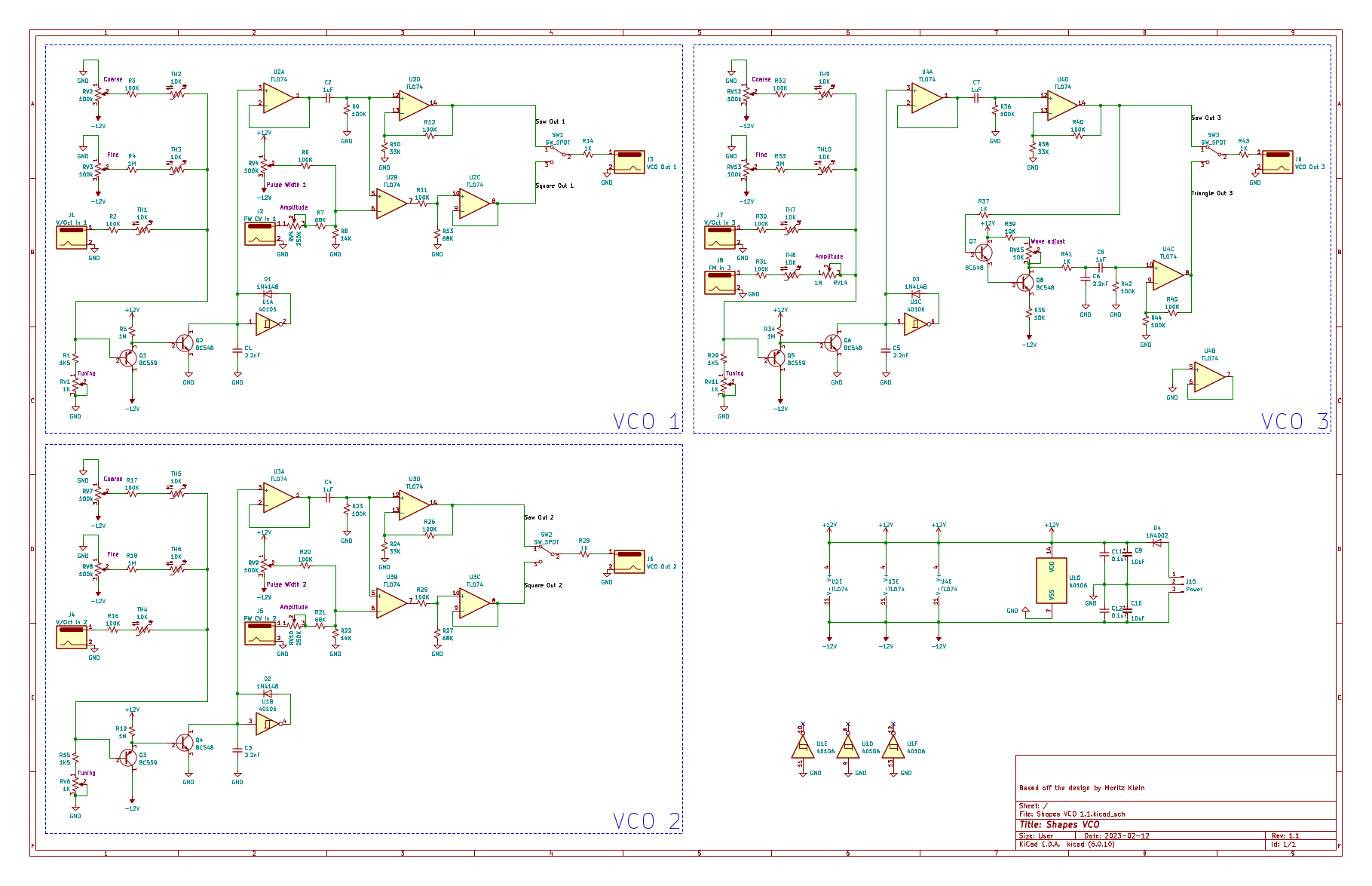
All 3 of the VCO's share a common CD4106 hex Schmitt-trigger. VCO 1 and 2 are identical and almost exactly as designed by Moritz. Each has both a coarse and a fine adjustment along with a volt-per-octave CV input. Each of the 3 inputs have a thermistor to help compensate for the temperature drift of the transistors supplying current to the oscillator. The first op-amp (A) is used to isolate the oscillator. It's output is connected to a high pass filter which is then ran through the second op-amp (D) to amplify the signal to the appropriate level as well as center the wave at 0 volts. The pre-amplified sawtooth signal is also sent to the third op-amp (B) without any kind of feedback. The lack of any feedback causes the op-amp to saturate either + or - based on the positive inputs voltage compared to the negative. By adjusting the negative input of op-amp, we can change the point in the waveform where the op-amp will swap its saturation to the opposite supply rail voltage. For adjusting this voltage, we have an additional potentiometer as well as another control voltage input. Adjusting either of these changed the pulse width of the square wave. The fourth and final op-amp (C) is again used to amplify and center the output. Finally we have a switch to send either the square or the sawtooth waveform to the output jack.
VCO 3 uses the exact same circuit for the sawtooth waveform as the other 2. Where it differs from Moritz design is that the output to the "squaring" op-amp is omitted. Instead, the amplified sawtooth waveform is sent to a pair of transistors to invert the signal and sum it with the original. The waveform is then sent to the final op-amp (C) via a bandpass filter to be amplified and centered. The forth op-amp (B) is not used and tied to ground to reduce noise. Also be sure to tie any unused inputs of the Schmitt-trigger to ground for the same reason. Because we have no use for a PWM CV input jack, I decided to add a FM CV input in it's place. This is great for adding a vibrato effect to the tone by connecting it to an LFO. If you're keen, you may have notice the bodge wire coming off of resistor R35. I
Tuning the Circuit
Tuning the VCO's is important if you actually want to use them to produce music and not just sound. Now, obviously, each of the oscillators tones can be adjusted by the potentiometers. What needs to be tuned, though, is the frequency when being controlled by the volts-per-octave control voltage. This is adjusted for VCO 1, 2 and 3 with trimmers RV1, RV6 and RV11, respectively.
What we need to do is plug in an input voltage that can be changed back and forth between 2 notes an octave apart. If you don't yet have a sequencer or keyboard that can output CV, you could use any voltage source input of 3.0v for A3 and 4.0v for A4. Once we have our 2 voltages set up and plugged into the V/Oct jack, we play the lower voltage and adjust the output with the coarse and fine knobs to reach the desired note. We will then switch over to the high voltage and, this time, use the trimmer pot to adjust the note to one octave above the first. We aren't done yet though. If we go back to the lower voltage, we will find it to now be out of tune. Once again we will have to use the coarse and fine adjusters to get the note output we desire. Then we repeat until switching between the 2 voltages gives us the desired precise 1 octave difference. For me this took a decent amount of fiddling but if the circuit was built correctly, you should eventually get it. As a side note, if you don't have access to a tuner of any kind, you can either tune by ear with a known tuned instrument or software, or you can do like I did and and use an oscilloscope. Tables with the frequency of each note can be easily found on the internet. We can then attach our probe to the output and set up 2 markers on the screen that correspond with the waveform peaks of the 2 notes we are tuning to. See the screenshots for more info.

The solid vertical white line marks the correct frequency of middle C.

The dotted vertical white line marks the correct frequency of C 4. Notice that the second peak lines up with the solid line! Each octave up is double the
frequency of the previous.


